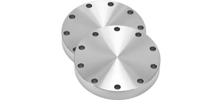
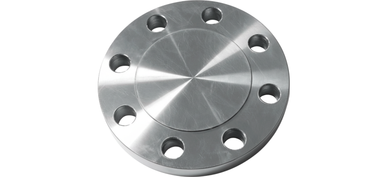
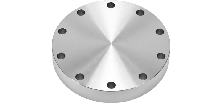
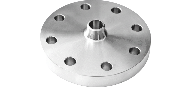
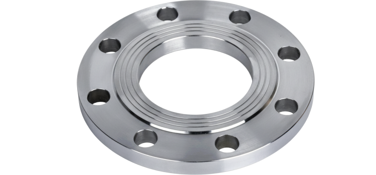
A BLIND FLANGE (BL) IS A SOLID FLANGE USED TO CLOSE THE END OF A PIPE, VALVE, OR PRESSURE VESSEL OPENING. IT HAS NO BORE AND IS BOLTED IN PLACE TO ALLOW EASY ACCESS TO THE PIPING SYSTEM FOR INSPECTION, MAINTENANCE, OR FUTURE EXPANSION. IDEAL FOR HIGH-PRESSURE APPLICATIONS, BLIND FLANGES PROVIDE A STRONG, LEAK-PROOF SEAL AND ARE COMMONLY USED IN INDUSTRIES LIKE OIL & GAS, POWER GENERATION, AND PETROCHEMICALS
Type
Solid flange with no bore.
Size Range
½” to 60” (DN15 to DN1500)
Custom sizes available on request
Pressure Class
ANSI/ASME: Class 150 / 300 / 400 / 600 / 900 / 1500 / 2500
DIN/EN: PN10 / PN16 / PN25 / PN40 / PN64
End Connections
Bolted to mating flanges with gasket seal
Compatible with RF / FF / RTJ
Body Materials
Carbon Steel (ASTM A105 / A350 LF2)
Stainless Steel (SS304 / SS316 / SS321 / Duplex)
Alloy Steel (ASTM A182 F11 / F22 / F91)
Others: Cast/Ductile Iron, Bronze, Brass, Copper, Nickel Alloys
Sealing Face Types
Raised Face (RF)
Flat Face (FF)
Ring-Type Joint (RTJ)
Tongue & Groove (T&G)
Standards
Design & Dimensions: ASME B16.5 (≤24”), ASME B16.47 (>24”), EN 1092-1, ISO 7005-1, BS 4504
Testing: API 598 / EN 12266
Applications
Pressure vessel heads, pipeline terminations, hydrostatic testing, temporary/permanent closures
Used in oil & gas, chemical, water treatment & power industries
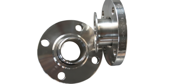
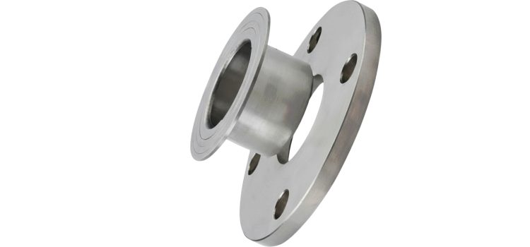
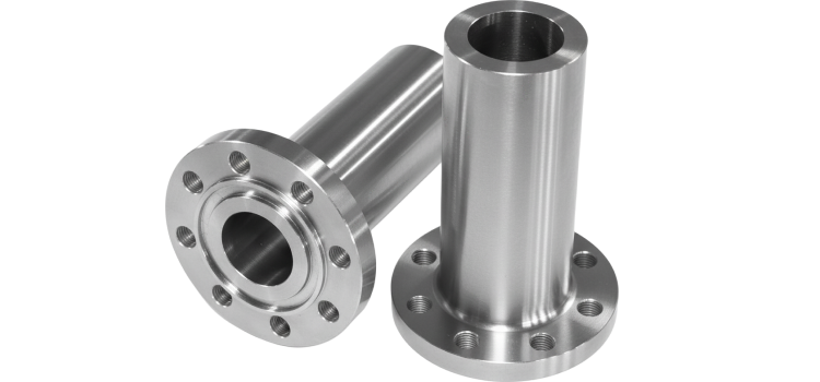
A LAP JOINT FLANGE (LJ) IS A TWO-PIECE FLANGE SYSTEM USED WITH A STUB END THAT IS WELDED TO THE PIPE. THE FLANGE I TSELF REMAINS LOOSE AND CAN ROTATE FREELY, MAKING IT I DEAL FOR FREQUENT ASSEMBLY/DISASSEMBLY AND EASY BOLT ALIGNMENT. OFTEN USED IN CORROSIVE OR HIGH MAINTENANCE ENVIRONMENTS, IT ALLOWS COST SAVINGS BY USING A CORROSION-RESISTANT STUB END AND A LOWER GRADE BACKING FLANGE
Type
Two-piece design consisting of:
• Lap Joint Flange (loose flange)
• Stub End (butt-welded to the pipe)
Flange rotates freely around the stub end – ideal for frequent dismantling, alignment, or space adjustments.
Size Range
½” to 24” (DN15 to DN600)
Custom sizes available on request
Cost-effective for larger diameters
Pressure Class
ANSI/ASME: Class 150 / 300 / 600
DIN/EN: PN10 / PN16 / PN25 / PN40
Generally suited for low to moderate pressure
End Connections
Requires stub end (butt-welded to pipe)
Rotating flange allows easy bolt alignment
Sealed with gasket between mating faces
Body Materials
Carbon Steel (ASTM A105 / A36)
Stainless Steel (SS304 / SS316)
Aluminum, Nickel Alloys & other non-corrosive materials
Sealing Face Types
Typically Flat Face (FF)
Also available in Raised Face (RF)
Seal is made on stub end face, not the flange
Standards
Design & Dimensions: ASME B16.5 (≤24”), EN 1092-1, ISO 7005-1, BS 4504
Testing: API 598, EN 12266
Materials & Welding: ASTM Standards, ASME Sec IX (stub end welding)
Applications
Systems requiring frequent dismantling or inspection
Corrosive media (SS stub ends with CS flanges)
Food processing, pharmaceuticals, shipbuilding, chemicals
Large diameter / costly piping materials for cost reduction
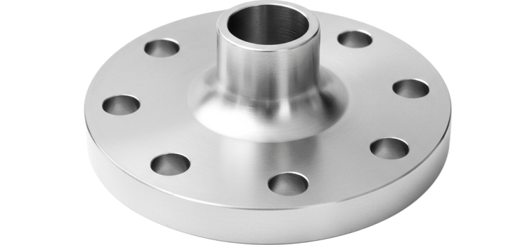
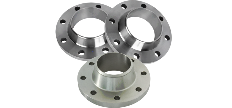
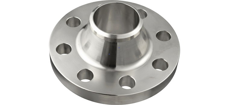
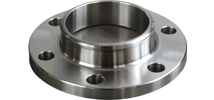
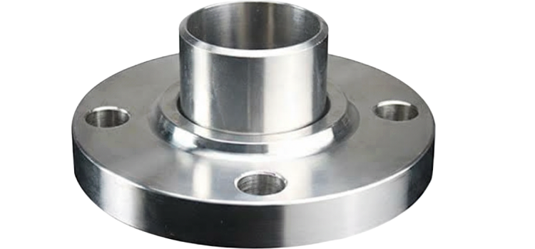
A WELD NECK FLANGE (WN) IS A HIGH-STRENGTH FLANGE DESIGNED WITH A LONG TAPERED HUB THAT IS BUTT-WELDED TO A PIPE. IT PROVIDES EXCELLENT STRESS DISTRIBUTION AND IS IDEAL FOR HIGH-PRESSURE, HIGH-TEMPERATURE, AND CRITICAL APPLICATIONS. COMMONLY USED IN OIL & GAS, POWER PLANTS, AND PETROCHEMICAL INDUSTRIES, IT ENSURES A SECURE, LEAK-PROOF CONNECTION AND MINIMIZES TURBULENCE AND EROSION AT THE JOINT.
Type
Long tapered hub with butt-welded connection
Designed for high-pressure & high-temperature applications
Ideal for critical services and vibration-prone systems
Size Range
½” to 60” (DN15 to DN1500)
Custom sizes available for special applications
Pressure Class
ANSI/ASME: Class 150 / 300 / 400 / 600 / 900 / 1500 / 2500
DIN/EN: PN10 / PN16 / PN25 / PN40 / PN64
Suitable for high-pressure systems (material & schedule dependent)
End Connections
Butt weld end integral to flange design
Matches pipe schedule for seamless welding
Machined to match pipe bore for smooth flow & reduced turbulence
Body Materials
Carbon Steel (ASTM A105 / A350 LF2)
Stainless Steel (SS304 / SS316 / SS321 / Duplex)
Alloy Steel (ASTM A182 F11 / F22 / F91)
Nickel Alloys, Copper Alloys, Titanium (per service needs)
Sealing Face Types
Raised Face (RF)
Ring-Type Joint (RTJ)
Flat Face (FF)
Male-Female (M/F)
Tongue & Groove (T&G)
Standards
Design & Dimensions: ASME B16.5 (≤24”), ASME B16.47 (>24”), EN 1092-1, ISO 7005-1, BS 4504
Testing: API 598, EN 12266, MSS SP-44
Materials & Welding: ASTM specifications, ASME Section IX (welding)
Applications
Oil & Gas, Petrochemical, Power Generation
High-pressure steam lines, Offshore platforms
Cryogenic & high-temperature services
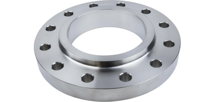
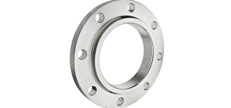
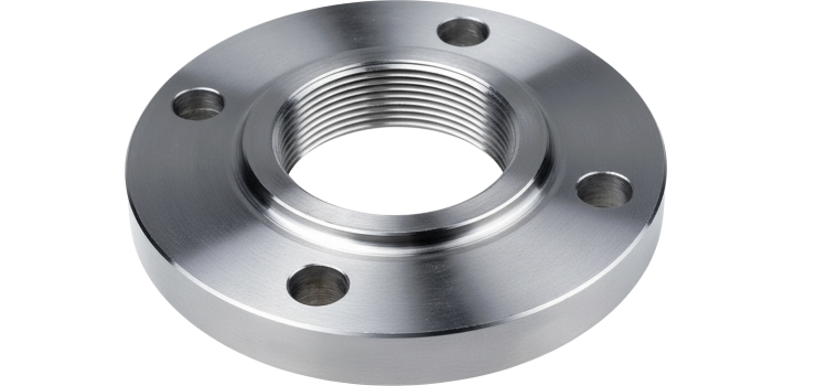
A SLIP-ON FLANGE (SO) IS A FLANGE THAT SLIDES OVER THE PIPE AND IS FILLET-WELDED ON BOTH THE INSIDE AND OUTSIDE TO PROVIDE STRENGTH AND PREVENT LEAKAGE. IT IS EASY TO ALIGN AND INSTALL, MAKING IT IDEAL FOR LOW- TO MEDIUM-PRESSURE APPLICATIONS. COMMONLY USED IN WATER, HVAC, AND INDUSTRIAL SYSTEMS, SLIP-ON FLANGES ARE COST-EFFECTIVE AND SUITABLE WHERE WELDING PRECISION IS LESS CRITICAL.
Type
Slides over the pipe and fillet-welded on both inner & outer edges
No tapered hub – flat face rests on the pipe
Easier alignment than weld neck flanges
Suitable for low to medium pressure, non-critical applications
Size Range
½” to 48” (DN15 to DN1200)
Custom sizes available on request
Pressure Class
ANSI/ASME: Class 150 / 300 / 400 / 600
DIN/EN: PN10 / PN16 / PN25 / PN40
Typically used in moderate pressure & temperature conditions
End Connections
Designed to be welded onto pipe ends
Matches pipe OD, not ID (requires accurate fitment)
Not suitable for beveled butt welds
Body Materials
Carbon Steel (ASTM A105 / A350 LF2)
Stainless Steel (SS304 / SS316 / SS321 / Duplex)
Alloy Steel (ASTM A182 F11 / F22)
Other Alloys: Copper, Nickel, Cast Iron, Ductile Iron, etc.
Sealing Face Types
Raised Face (RF)
Flat Face (FF)
Ring-Type Joint (RTJ) – less common for SO
Standards
Design & Dimensions: ASME B16.5 (≤24”), EN 1092-1, BS 4504, ISO 7005-1
Testing: API 598, EN 12266
Materials & Welding: ASTM specifications, ASME Section IX
Applications
Water & wastewater systems
Fire protection systems
HVAC & general industrial piping
Non-critical oil & gas or chemical systems
Ideal for frequent disassembly & cost-effective installation
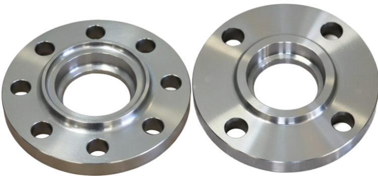
A SOCKET WELD FLANGE (SW) IS DESIGNED FOR SMALL DIAMETER, HIGH-PRESSURE PIPING SYSTEMS. IT FEATURES A RECESSED SOCKET INTO WHICH THE PIPE IS INSERTED AND FILLET-WELDED AROUND THE OUTER EDGE. THIS DESIGN PROVIDES A STRONG, LEAK-RESISTANT JOINT WITH SMOOTH FLOW CHARACTERISTICS. COMMONLY USED IN STEAM, HYDRAULIC, AND CHEMICAL SYSTEMS, SOCKET WELD FLANGES ARE IDEAL WHERE SPACE IS LIMITED AND HIGH INTEGRITY IS REQUIRED.
Type
Features a recessed socket for pipe insertion
Fillet-welded only on the outer side
Provides smooth bore & good flow characteristics
Suitable for small-bore, high-pressure piping systems
Size Range
½” to 4” (DN15 to DN100)
Typically for small-diameter pipes
Custom sizes available on request
Pressure Class
ANSI/ASME: Class 150 / 300 / 600 / 900 / 1500
DIN/EN: PN10 / PN16 / PN25 / PN40
Suitable for moderate to high pressure & temperature
End Connections
Socket weld connection
Pipe inserted into socket & fillet welded externally
Strong, leak-proof joint for small sizes
Not recommended for cyclic or dynamic loading
Body Materials
Carbon Steel (ASTM A105 / A350 LF2)
Stainless Steel (SS304 / SS316 / SS321 / Duplex)
Alloy Steel (ASTM A182 F11 / F22)
Other materials: Brass, Bronze, Copper Alloys, Nickel Alloys (on request)
Sealing Face Types
Raised Face (RF)
Flat Face (FF)
Ring-Type Joint (RTJ)
Standards
Design & Dimensions: ASME B16.5 (≤24”), EN 1092-1, ISO 7005-1, BS 4504
Testing: API 598, EN 12266
Materials & Welding: ASTM specifications, ASME Section IX
Applications
High-pressure steam systems
Chemical & petrochemical plants
Power generation
Hydraulic & compressed air systems
Ideal for small pipe sizes in high-integrity services
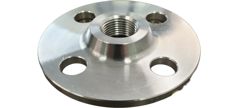
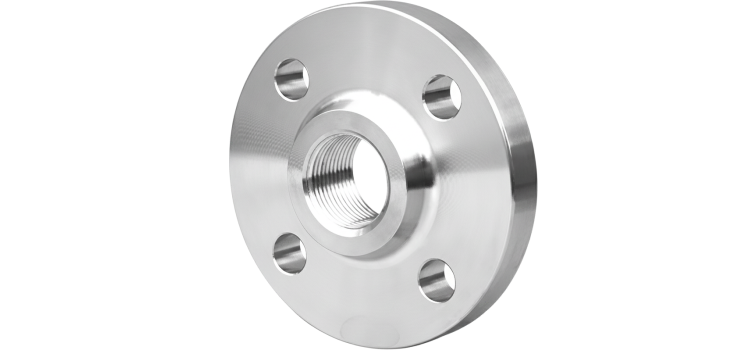
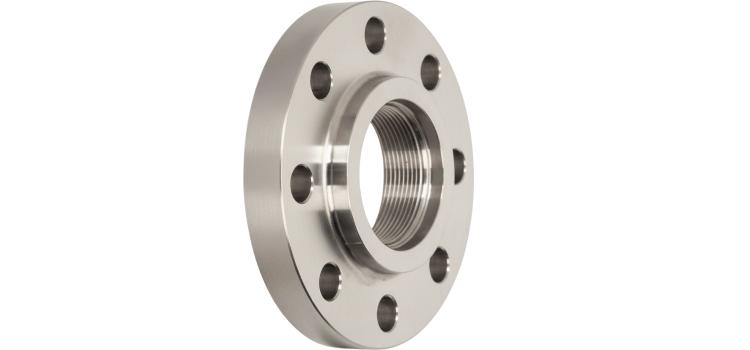
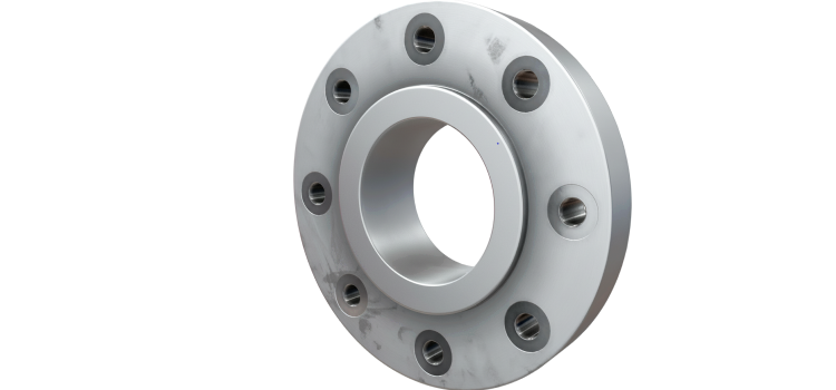
A THREADED FLANGE (ALSO KNOWN AS A SCREWED FLANGE OR SCRD FLANGE) IS DESIGNED WITH INTERNAL THREADS THAT ALLOW IT TO BE SCREWED DIRECTLY ONTO A PIPE WITHOUT THE NEED FOR WELDING. IT IS IDEAL FOR LOW-PRESSURE AND NON-CRITICAL APPLICATIONS, ESPECIALLY IN FLAMMABLE OR EXPLOSIVE ENVIRONMENTS WHERE WELDING IS HAZARDOUS. COMMONLY USED IN FUEL LINES, COMPRESSED AIR SYSTEMS, AND UTILITY PIPING.
Type
Internal threads allow flange to be screwed onto pipe without welding
Commonly used in low-pressure, non-critical applications
Ideal for flammable or explosive environments where welding is unsafe
Also known as Screwed Flange (SCRD)
Size Range
½” to 4” (DN15 to DN100)
Custom sizes available on request
Pressure Class
ANSI/ASME: Class 150 / 300 / 600
DIN/EN: PN10 / PN16 / PN25
Typically used in low to moderate pressure systems
End Connections
Threaded (screwed) connection – no welding required
Standard threads: NPT (ASME B1.20.1) or BSP (ISO 7-1 / EN 10226)
Optional seal weld can be applied for added strength & leak protection
Body Materials
Carbon Steel (ASTM A105 / A350 LF2)
Stainless Steel (SS304 / SS316 / SS321)
Alloy Steel (ASTM A182 F11 / F22)
Others: Brass, Bronze, Copper Alloys, PVC, Gunmetal (special applications)
Sealing Face Types
Raised Face (RF)
Flat Face (FF)
Ring-Type Joint (RTJ) – less common
Standards
Design & Dimensions: ASME B16.5 (≤24”), EN 1092-1, ISO 7005-1, BS 4504
Thread Standards: ASME B1.20.1 (NPT), ISO 7-1 / EN 10226 (BSPT/BSPP)
Testing: API 598, EN 12266
Applications
Low-pressure systems
Fuel, gas & explosive environments
Compressed air & instrumentation lines
Plumbing & utility services
Temporary or easily disassembled piping systems
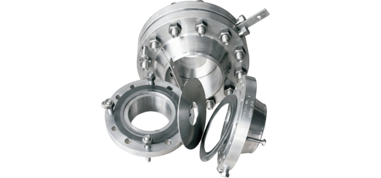
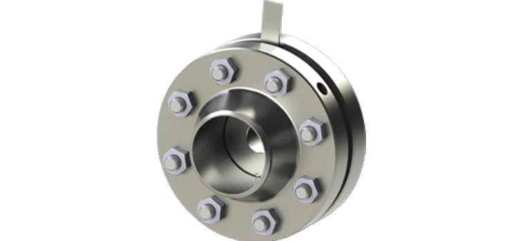
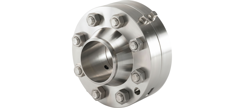
AN ORIFICE FLANGE IS A SPECIALIZED FLANGE USED FOR FLOW MEASUREMENT IN PIPELINES. IT IS DESIGNED TO HOLD AN ORIFICE PLATE AND INCLUDES PRESSURE TAP HOLES TO MEASURE DIFFERENTIAL PRESSURE ACROSS THE PLATE. COMMONLY USED IN OIL & GAS, CHEMICAL, AND UTILITY SYSTEMS, IT PROVIDES ACCURATE FLOW MONITORING AND IS BUILT TO WITHSTAND HIGH-PRESSURE ENVIRONMENTS. ORIFICE FLANGES ARE MANUFACTURED PER ASME B16.36 AND ARE COMPATIBLE WITH STANDARD PIPING FLANGES
Type
Specialized flange assembly used with an orifice plate to measure fluid flow rate in pipelines
Supplied as a pair of flanges with:
– Pressure tap holes (for differential pressure measurement)
– Jack screws (to separate flanges for plate removal)
Used with flow meters or transmitters
Size Range
1” to 24” (DN25 to DN600)
Custom sizes available for larger/specialty applications
Matches piping and flow equipment sizes
Pressure Class
ANSI/ASME: Class 150, 300, 600, 900, 1500, 2500
DIN/EN: PN10, PN16, PN25, PN40, PN64
Must match system and process conditions
End Connections
Typically flanged – compatible with weld neck or slip-on types
Bolted to standard pipe flanges or fittings
Includes tapped ports (¼” NPT or similar) for pressure instruments
Body Materials
Carbon Steel: ASTM A105, A350 LF2
Stainless Steel: SS304 / SS316 / Duplex
Alloy Steel: ASTM A182 F11 / F22
Other materials (Hastelloy, Monel, etc.) available for specific media
Sealing Face Types
Raised Face (RF)
Ring-Type Joint (RTJ) – common in high-pressure services
Gasket type selected per application and pressure rating
Standards
Design & Dimensions: ASME B16.36 (Orifice Flanges), ASME B16.5, ASME B16.47, EN 1092-1
Testing: API 598 (pressure), EN 12266 (leak testing)
Measurement: ISO 5167 (orifice flow measurement)
Applications
Flow measurement of gases, steam, or liquids
Used in oil & gas, chemical plants, power generation, water treatment
Installed with orifice plates and differential pressure transmitters
Suitable for clean and moderately dirty process fluids
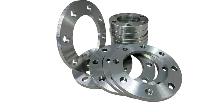
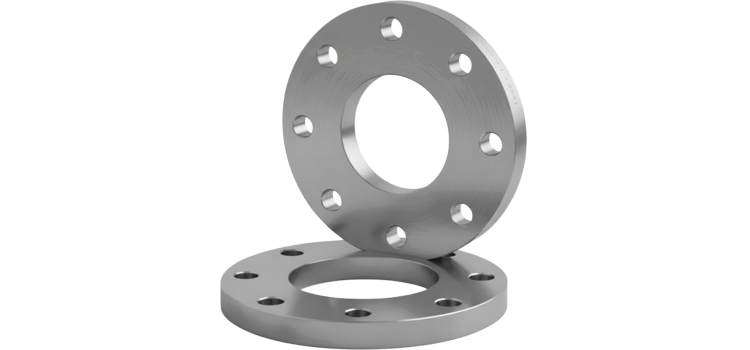
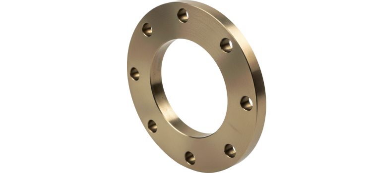
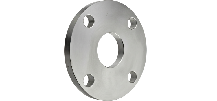
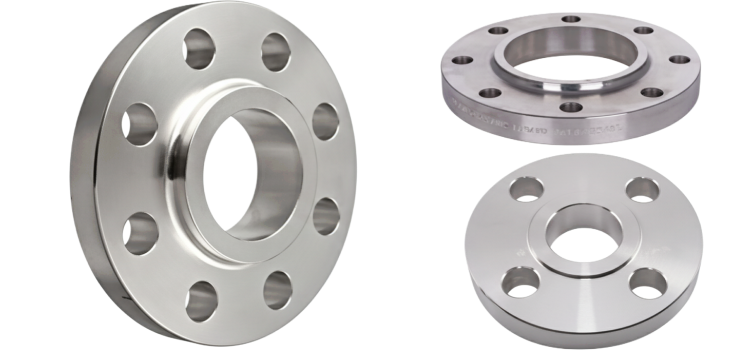
A PLATE FLANGE IS A SIMPLE, FLAT FLANGE MADE FROM A SINGLE METAL PLATE, USED TO CONNECT PIPES OR EQUIPMENT I N LOW-PRESSURE PIPING SYSTEMS. IT IS FILLET-WELDED DIRECTLY TO THE PIPE AND FEATURES BOLT HOLES FOR SECURE FASTENING. DUE TO ITS COST-EFFECTIVENESS AND EASE OF FABRICATION, PLATE FLANGES ARE WIDELY USED IN WATER SUPPLY, HVAC, FIRE PROTECTION, AND GENERAL INDUSTRIAL SERVICES WHERE HIGH PRESSURE AND TEMPERATURE ARE NOT A CONCERN.
Type
Flat, circular disc with bolt holes around the perimeter and a central bore
Made from a single metal plate, without a hub or taper
Welded directly to the pipe (typically fillet weld)
Economical and simple design, suited for low-pressure, non-critical applications
Size Range
½” to 48” (DN15 to DN1200)
Custom sizes available
Widely used in light-duty and general-purpose piping systems
Pressure Class
ANSI/ASME: Class 150, 300 (typically up to 300)
DIN/EN: PN6, PN10, PN16, PN25
Not recommended for high-pressure or high-temperature services
End Connections
Welded (fillet weld to pipe’s outer surface)
Easy to fabricate and install
No beveling required (unlike weld neck flanges)
Body Materials
Carbon Steel: ASTM A105, A36
Stainless Steel: SS304 / SS316
Mild steel, galvanized steel, alloy steel
Also available in aluminum, bronze, cast iron for specific industries
Sealing Face Types
Flat Face (FF) – most common
Raised Face (RF) – less typical for plate flanges
Standards
Design & Dimensions: EN 1092-1 Type 01 (Plate Flange – Plain), ASME B16.5 (rare), BS 4504, ISO 7005-1
Testing: EN 12266, API 598 (system pressure testing)
Applications
Low-pressure water pipelines
Fire protection systems
General industrial or structural piping
HVAC, irrigation, utility networks
Common in non-critical and cost-sensitive projects